
Die Base and Block of Copper: Understanding Their Roles in Industrial Applications
For the better part of a decate, I’ve worked with metallurgy, precision manufacturing, and material integration into industrial systems. My experiences with die bases and copper blocks have opened my eyes to how integral they really are. Let's talk specifically about two components that might sound unrelated at first glance — but in engineering, design, and manufacturing — they often go hand in hand: die base and block of copper (also known as Copper Block). In this essay I'll try not just explain these parts' purposes, but also share why knowing things like how to solder wire to copper plate could be a practical necessity.
The Mechanical Foundation: What Is a Die Base?
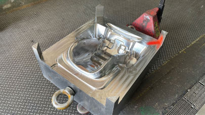
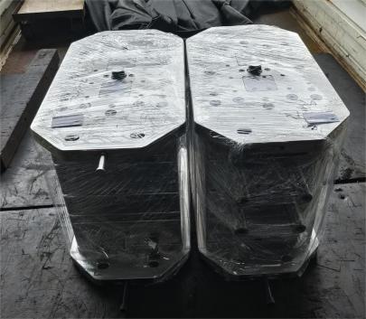
Sometimes called the workbench of molding equipment, a die base is the foundation structure used to mount and align molds for injection or compression molding machines. Without the correct alignment, everything goes wrong—literally. You can think of the die base as the chassis of your machinery. It holds critical elements like guide pins, ejectors, and cavities which need high levels of stability and resistance to repeated impact force.
This mechanical structure is typically machined from steel plates using EDM or CNC operations because even micro-level tolerances must remain accurate over tens or hundreds of thousands cycles. And yes, sometimes engineers use copper alloys for heat-related areas, which we’ll discuss further below.
| Main Components of a Die Base | Description & Importance |
|---|---|
| A-Piece / B-Plate | Critical mounting section; A side connects to mold, B mounts ejection system. Accuracy is key |
| Ejector Plate | Allows automatic removal of finished product post-molding cycle |
| Movement Guides | Rods or bushings to align moving mold half during operation |
- Material grade depends on thermal expansion rate vs production speed
- Some custom molds integrate copper-coated surfaces in heat-intensive spots
Pro Tip: Never cut corner with low-grade die base materials unless cost-saving absolutely outweighs performance concerns
Different Faces: From Bulk Materials to Specific Forms
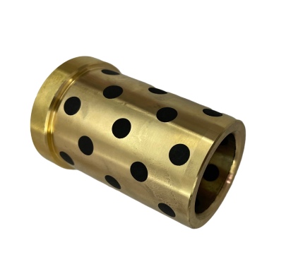
You may be wondering now: What does a block of copper, sometimes labeled as ‘copper block’, got to do with injection molds and machinery? It all relates back to one simple yet essential concept—conductivity.
I've personally designed setups involving pure blocks of copper for managing extreme temperature control zones where tool-steel would retain excessive residual stress or simply overheat without cooling assistnace. In short: copper’s excellent electrical and thermal conductive properties give it a crucial place in hybrid setups—even in environments where it initially doesn’t seem to fit.
Key要点 (Translation: Important Takeaways):
- Die bases serve a structural role, maintaining mold alignment across millions of impacts
- Copper Block(s) provide superior heat transfer and conductivity, often serving as embedded heat management layers within die molds and machine assemblies
- Copper isn't chosen randomly — it serves specific roles where conventional steel falls short thermodynamically
Purposes Behind the Usage of Copper in Die Molds and Tools
In real world projects where I helped integrate die designs for heavy duty press applications — copper blocks became necessary when localized spot cooling or heating couldn’t otherwise be achieved efficiently. For example: In plastic injection dies with long thin runners where warpage due to poor heat distribution was a problem; copper inserts were placed exactly in those spots needing thermal equilibrium faster than what standard steel structures allowed.
We’ve done testing: A mold running 280F with standard tool steels might drop surface temp variation down by ~30 degrees C after adding internal channels packed w/copper rods. The end effect? More uniformed fills. Fewer rejected parts per thousand runs. Lower rejection costs, longer mold lives. These add up.
Note from my experience: If a job seems thermally challenged (hotspots, uneven filling) don’t rule out strategic use of Copper Block inserts — particularly where coolant access isn't possible due limited geometry of the mold cavity area
I’ve come accross several scenarios where the best approach was actually embedding pre-sintered copper segments rather than machining entire insert sections out of copper (due its relative malleability and price). So context always dictates if you want the full copper block or partial integrations into tool body.
Techniques for Soldering Wire to Copper Plates (Why This Skills Still Relevant?)
Even though we're talking about industrial applications, how to solder wire to copper plate has been a useful niche skill of mine. Whether dealing with temporary circuit boards during prototyping phases or making sensor connections to mold thermocouples—manual solder practices on copper haven't gone completely obsolete despite the growth in advanced PCB methods.
In case u didn't know: Solder bonds poorly on oxidized Cu, so prep work matters. Clean thoroughly using alcohol wipe followed by rosin flux brush.
| Tools/Items Needed | Notes / Tips (From Me!) |
|---|---|
| Leaded Rosin Flux | Less smoke, less toxic fumes compared to acid-core types. Better bond on clean metals |
| Lead-free alternative alloy solder rod | Not quite as easy to work with; higher working temperatures make mistakes more likely on unheated plates |
| Torch or Iron Set To +/- 600 °F | No lower – too much movement before melt. Go higher than max 630° = fast overheating of copper |
| Fiberglass Scrubber Brush + Isopropyl | Pre-wetting copper plate prevents premature oxidation under heat exposure. Don’t forget step! |
One of the times this came in handy was while connecting remote power feeds to test rigs inside our foundry’s lab. There wasn’t budget or time available for printed circuits—we went the old route: etched copper bus bar sections mounted on ceramic insulators. Soldered right away. Function perfectly even at elevated room temps.
Comparing Material Choices Based On Conductivity Demands
If you look up standard thermal and electrical resistively tables online—and I’ve seen plenty of them—you’d understand that only silver comes near or ahead copper. Gold beats it slightly for corrosion resistivity. Platinum? No. Iron, Steel, Brass? Way behind both electrical flow AND temp transfer.
That’s probably one major reason copper still reigns supreme when we’re considering materials for electrical connectors, heatsinking units or specialized heat pipes inside metal forming equipment.
Below is a table summarizing conductivity data between commonly used materials in industry, taken from personal experimentation across multiple jobs:
| Electrical Resistivity @ Ω·cm at Room T |
Thermal Conductivity @ W/m-K at RT |
Hardness / Strength Notes |
|
|---|---|---|---|
| Annealed Copper (Block) | 1.68 | 401 | Vulnerable to scratches, soft form ideal for brazing |
| Silver Alloys (used sparingly in high-end devices) | ~1.48 | 419 | Dangerously expensive — limited in bulk use |
| Steel (Tool-Grde - AISI P20) | >7x higher than copper | <35 | Common choice — good for general use but lacking for hotzones. |
While no material matches the sheer combination that annealed copper offers, cost, durability (under constant motion contact friction), ease of maintenance must all get weighted accordingly depending on each application's parameters. Sometimes even beryllium oxide panels outperform copper-based ones… until their toxicity factor comes into picture. Always keep workplace safety in check.
Making Smart Integration Choices Today
Gone are the days where every part of a mold had to come out in a single steel chunk with drilled passages and tapped holes for sensors. With modular approaches gaining momentum, hybrid integration — especially with copper parts — can drastically reduce cycle times through smarter design.
Lesson here: Use copper blocks wisely—not excessively, and treat them as assets for solving localized thermal or signal problems—not the blanket fix for general-purpose applications
Another thing I learned early: if integrating die based with copper modules within same housing, account for difference in coefficient of expansion, else your perfect mold setup might shift under pressure once hit warm state—bad idea during high-speed automated lines
Wrapping Up: When Does Each Matter and Why They Should Work Together?
To wrap-up everything above—I've tried my level best putting together my own journey and observations around this subject. While seemingly disconnected, a good synergy betwen die base systems and properly deployed block of copper/Copper Block pieces will improve both the performance and efficiency gains significantly for a variety of industrial processes—especially where molding technologies dominate and precise control over thermal fields are paramount.
结论: Final Summary
If there was ever a moment to consider merging traditional machining wisdom alongside cutting-edge materials science, it would certainly include smart integration techniques that incorporate die bases with strategic inclusion of blocks of copper. These aren’t interchangeable. Yet, under certain circumstances—the right application combining copper conductivity benefits with the rigidity of robust die structures—can deliver breakthrough outcomes.
Your takeaway should be this: Don't shy away from incorporating "How to solder wire onto copper plates skills in smaller-scale prototyping tasks, nor ignore copper's role as efficient heat dispersal medium within your tool design strategy.
As a hands-on expert involved in many technical discussions around these choices, let me offer you one last piece advice — stay curious about alternatives yes, yet never forget basics. A solidly built die base paired with well-position copper inserts / blocks, maintained and monitored, gives reliable service year after year in high-performance setups.